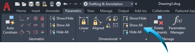
PARAMETRIC CONSTRAINTS
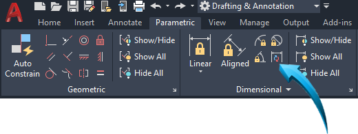
Drafting & Annotation | Parametric
Definition
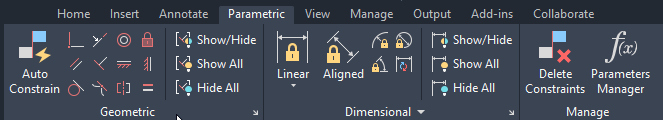
Parametric Constraints constrain the geometry of a sketch to specific conditions, eg: perpendicular; parallel, equal radius, tangent. etc. These are referred to as geometric constraints and are displayed in the palette above.
Dimensional constraints apply linear, angular, diametric and radial constraints to objects to define measurement and spatial relationships.
Auto-Constraints can be automatically added to a sketch when their geometry is implied. For example, when drawing a simple rectangle, geometric constraints are applied to make the opposite lines of the rectangle parallel to each other, makes coincident the end points of the lines, and constrains all connecting angles to 90º, making them perpendicular.
Constraints can either be implied at the start of the sketch, meaning the are activated prior to creating the sketch by activating the Infer Constraints tab at the base of the editor, or they can be added after the creation of the sketch profile using Auto Constrain, shown in the ribbon above left.
Below is an example of an auto-constrained sketch showing auto-constraints activated before drawing a rectangle with filleted corners. Auto-Constraints shown are parallel and perpendicular
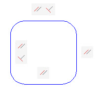
Implied constraints automatically added
Below is an example of the Auto Constrain tool being applied after the sketch profile is created, with constraints added after completion of the sketch profile using Auto Constrain. Constraints shown below are parallel, perpendicular , tangent and horizontal  .
.
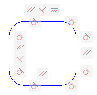
Additional constraints added
 Video Tutorial
Specific Purpose Exercise | Constrained Sketch
Constraint Conditions
Drafting & Annotation | Parametric
The following conditions apply to geometric and dimensional constraints
- Constraints can either be automatically applied to a sketch using the Infer Constraint tab at the base of the graphics editor, or can be added later using
- All implied constraints can be added to a sketch using Auto Constrain, shown below.
- Constraint markers can be deleted when necessary using the Delete tool or can be hidden using the Show/Hide function, shown in the palette above..
- When a dimensional constraint is deleted, the implied association with the constrained object is removed.
- When inserting dimensional constraints, the osnaps are deactivated for the duration of the task. Dimensional constraints utilize their own object snap geometry.
Infer Constraints
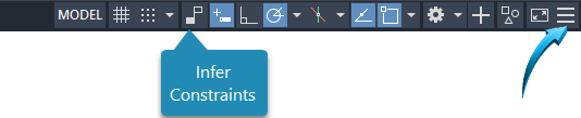
When this tab is activated, implied constraints are automatically added to each object during the sketch process. To show this option in the Status Bar, select the customization icon in the extreme lower right of the editor, shown by the arrow below right. Select Infer Constraints from the context menu. This adds the Infer Constraints tool to the Status Bar, shown below.
For example, when drawing a simple rectangle, geometric constraints are applied to make the opposite lines of the rectangle parallel to each other, makes coincident the end points of the lines, and constrains all connecting angles to 90º, making them perpendicular, similar to the example below.

Rectangle with parallel and perpendicular constraints automatically added using Infer Constraints
In the illustration above, the arrow indicates a Parallel Constraint. A parallel constraint will always have a 'paired' parallel constraint to which the selected constraint is parallel. This is indicated in the illustration above by both associated parallel constraints highlighting when one is selected.
Show / Hide Constraints
Drafting & Annotation | Parametric | Geometric
The symbols in the illustration above are referred to as geometric constraint markers and can be viewed or displayed using the Show/Hide function above.
When a dimensional constraint is deleted, the implied association with the constrained object is removed.
Auto Constrain

Drafting & Annotation | Parametric | Auto Constrain
Applies geometric constraints to an object after it has been drawn, similar to the illustration below. In this example, the sketch was created, then the geometric constraints added using the Auto Constrain tool.
In the example below, the 'paired' constraint, collinear is shown by the arrow. This indicates that both points are in a parallel plane.
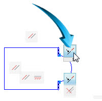
Post-sketch constraints added using Auto Constrain. Arrow shows the 'paired' collinear constraint.
Using the Properties Palette to update Constraints
The Properties palette can be used to update single instances of constraints, such as the constraint name and value, but it is generally recommended that the Parameters Manager palette be used for this task as all associated constraints can be viewed in context.
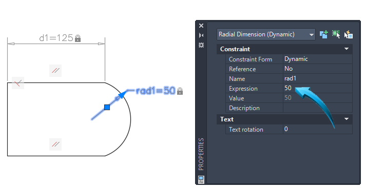
Using the Properties palette to update a constraint
Constraint Compliant Objects
Definition
Geometric and dimensional constraints can be used on most drawing objects, however, compound entities such as polylines, rectangles and closed polygonal shapes should preferably be exploded prior to applying constraints.
Geometric and dimensional constraints cannot be used to constrain ellipses, splines and construction entities.
Additionally, constraints cannot be applied to compound objects such as Blocks, Symbols and Groups unless such objects are exploded into their constituent parts.
Constrained sketches can be formatted into Groups, Blocks or Symbols, but will require exploding after insertion into a drawing.
Geometric constraints can be deleted in the same manner as a drawing object. When a constraint is selected, its corresponding (paired) constraint will be highlighted and deleted.
Similarly, dimensional constraints can be deleted in the same manner as a drawing object, however all associated parametric information and formulas will be deleted from the Parameters Manager palette.
In the example below, the constraint is added as 'Length'. The Length parameter of 120 is then updated to 80, shown as item 2.
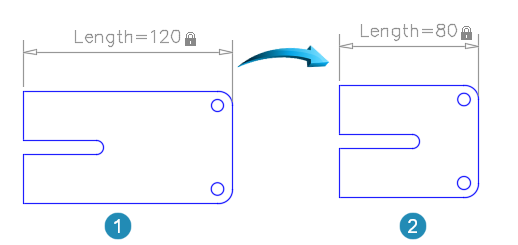
Updating constraints on a 2D sketch
Parameters Manager
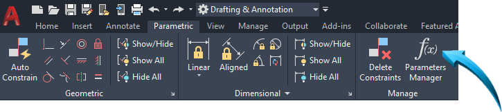
Drafting & Annotation | Parametric | Manage
Definition
Dimensional constraints and conditions, referred to as Design Rules are modified in the Parameters Manger palette, shown above.
Variable names are supplied on each insertion of a dimensional constraint and are usually listed sequentially as d1, d2 for linear constraints and dia1, dia2 etc for diametric constraints. The constraint names can be changed to better identify the objects if necessary.
In instances where multiple sketches are being constrained in the workspace, it is helpful to use the Filters feature, shown below, which allows constraints to be created for different sketch profiles.
In the example below, the Filters are used to create dimensional constraint parameters for the Baseplate and Extruded Top Profile.
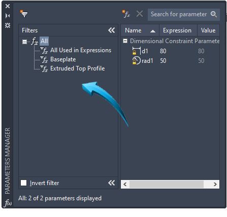
Parameters Manager showing Filters for 2 constrained sketches
Formulas and Design Rules
Definition
Formulas are used to define the relational and spatial values between objects and to create predictive behavioral patterns when associated constraints are modified.
Simple formulas are used to fix an object's position in relation to other objects and are commonly referred to as a Design Rule.
Design Rules are dimensional and geometric conditions created to maintain design integrity.
It is frequently necessary however, to assign a design rule which is unconditional. For example, when a rectangle has been drawn with a hole in the middle which is equidistant from all 4 sides, it is necessary that the hole maintain this relationship with the center line, irrespective of whether the length and width or the rectangle is lengthened or shortened.
In the example below, the inside diameter (IDia) is constrained such that it always maintains a measurement of 10 less than that of the outside diameter (ODia)
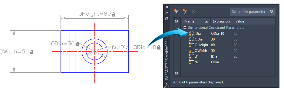
Constrained drawing with Formulas. Illustration
Geometric Constraint Features
Drafting & Annotation | Parametric | Geometric
Definition
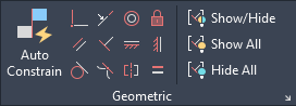
The Geometric palette, shown above, inserts geometric constraints into a 2D sketch to create a geometric relationship between objects and to impose predictive behavioral patterns when associated objects are modified.
The Auto Constrain tool, shown above is used to insert geometric constraints when the sketch is finished, or during the sketch process.
To insert constraints automatically during the sketch process, activate the Infer Constraints tab at the base of the graphics editor or click onto the expand arrow in the Geometric palette and select the Infer Geometric Constraints option.

Below is a description of the features and functions of geometric constraints.
 Coincident
Moves the position of a line or arc so that its end vertex is exact in location to the vertex of the line to which it is being made coincident. The planar geometry of the moved object is maintained.
 Collinear
Moves the end vertex of a selected line so that it is collinear with the projected parallel point of another vertex.
 Concentric
Fixes concentricity between 2 circles or arcs. Concentricity is maintained when the circles are moved or modified.
 Fix
Fix
By fixing the geometry of an object, its coordinate position is fixed and it will not move or rotate with its associated objects.
 Parallel
Adjusts the planar integrity of the first line so that it aligns to a parallel plane with the second line.
Perpendicular
Applies a 90º relationship between 2 lines. The first selected line is rotated so that it is in 90º aspect to the second line selected.
Horizontal
Constrains a line to the horizontal using the first point of the line as the horizontal reference.
 Vertical
Constrains a line to the vertical using the first point of the line as the vertical reference.
 Tangent
The tangent constraint moves a circle or arc so that it is tangential to a line. The circle always moves to the line; the line never moves to the circle.
 Smooth
Connects 2 splines with a predictable curve.
 Symmetric
The Symmetric constraint maintains a spatial relationship between objects across a symmetrical mirror line. When the symmetric constraint has been applied to circles, it will make both radii equal to each other.
 Equal
Equal
Makes 2 lines, circles or arcs equal in value to the first selected object.
Dimensional constraint features
Definition
When dimensional constraints are activated, they automatically and temporarily override the Osnap activation. Consequently, it is not necessary to activate any object snap modes as all dimensional constraint snap modes are implied.
Linear, including Horizontal / Vertical and Aligned constraints can be added to a sketch, and diameter and radius constraints can be added to circles and arcs.
When inserting a dimensional constraint, a constraint marker will highlight the implied geometric point, shown by the arrow, below. This attaches, in this example, to the endpoint or intersection point of the 2 lines.
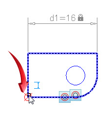
When a constraint marker does not target a specific point of geometry, a dimensional constraint cannot be added in that position.
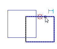
When using linear constraints, endpoints and midpoints of lines can easily be targeted by the constraint marker, but an intersection point of 2 intersecting closed polygons or lines cannot be used.
In the example below, the constraint marker finds the midpoint of the edge of the rectangle, but not the intersection point.
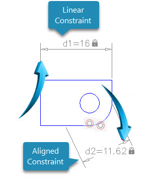
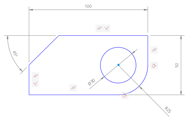
In the illustration below, a linear and aligned constraint is shown.
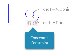
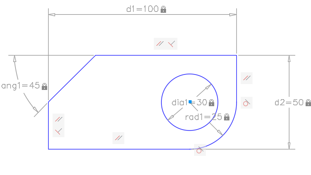
In the illustration below, a diameter and radial constraint is shown. In the illustrations above and below, the 2 circles have been constrained concentrically, shown by the geometric constraint.
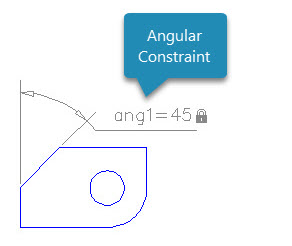
Angular constraints are used to constrain the angle between 2 lines or polylines, shown below
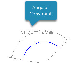
Angular constraints are also used to constrain the angle of an arc between the start and end point, shown below.
converting annotative dimensions to constraints
Drafting & Annotation | Parametric | Dimensional
Definition
When dimensions are inserted associatively to an object, they are inherently connected to the geometric properties of the object and will automatically be updated when the object is modified.
A dimension is not associated to an object when it has either been exploded or the dimensional value changed manually.
Only dimensions which have been inserted associatively with the dimensioned object can be converted to dimensional constraints.
In the illustration below, annotative dimensions have be inserted associatively to the object.
Sketch object with associated annotative dimensions
These objects are subsequently converted to dimensional constraints, shown in the illustration below.
Associative dimensions converted to constraints
When annotative dimensions have been converted to dimensional constraints, the values are automatically added to the Constraints Manager palette, shown below.

Constraints converted from Annotative Dimensions. Values added to Parameters Manager
